
Along those lines, I recently had an idea to hopefully show the studs in a little more realistically. I ran into a few roadblocks but thought I would post the results anyways. Maybe you have some additional ideas to share!
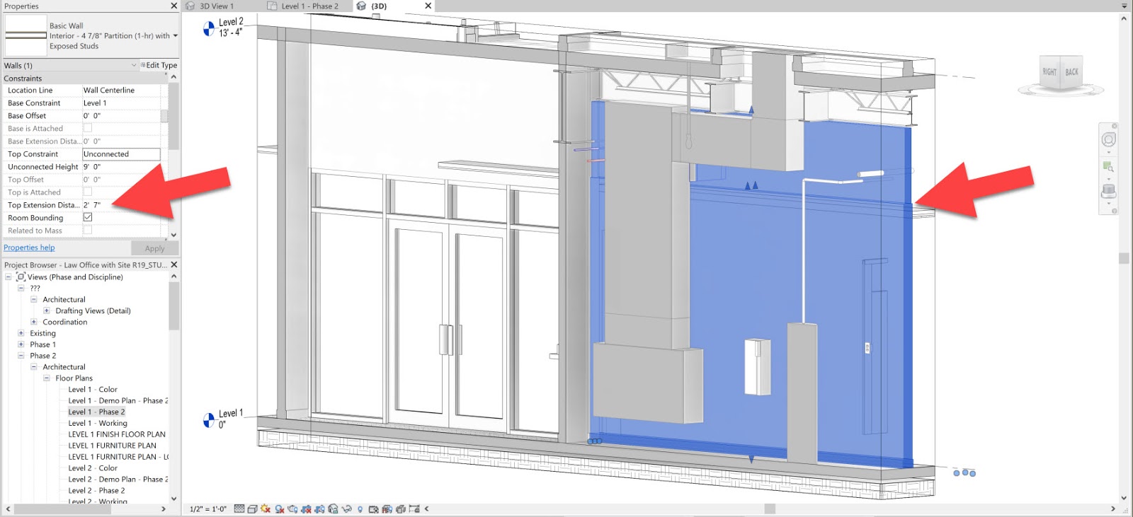
Before getting into the stud graphics, I will share a tip that allows you to disconnect the gypsum board layers from the stud layer. Not ideal for security and acoustic reasons, but it is not uncommon for the studs to extend to the structure above, and the gypsum board layers to stop just above the ceiling. Revit can handle this in the normal wall type as shown in the first image below.
Here is how that is done...
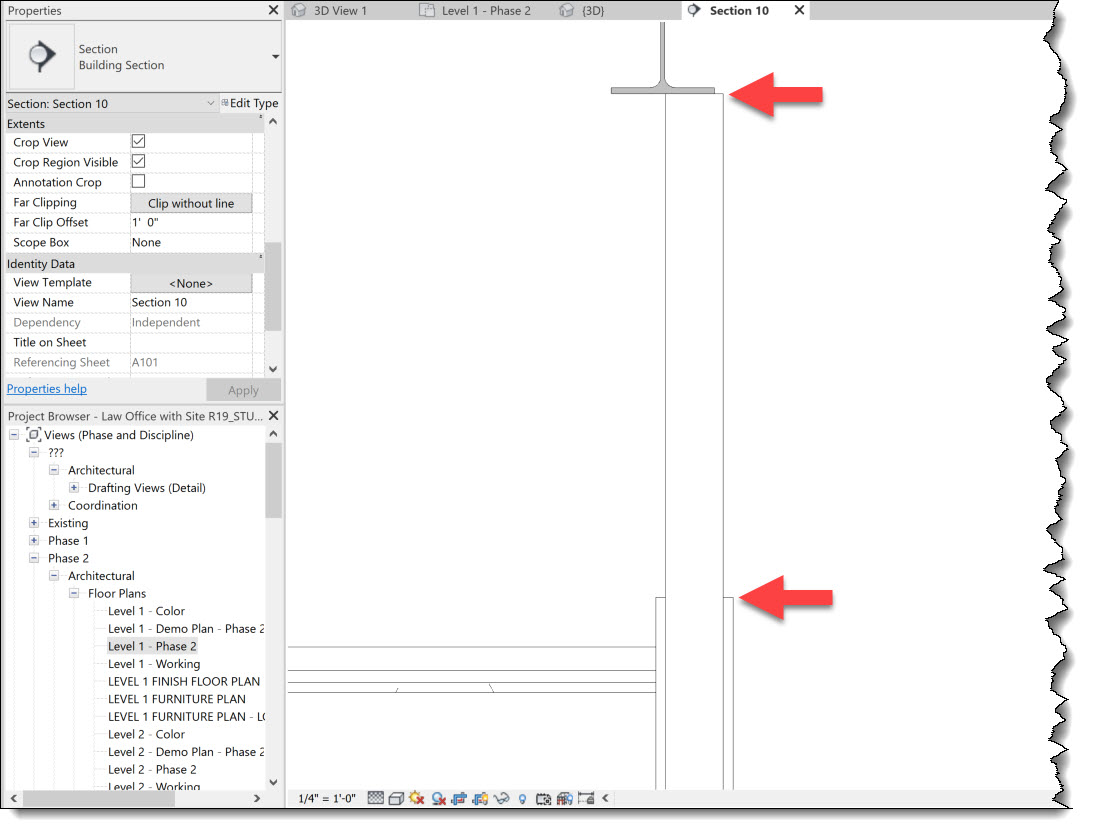
While editing the wall type Structure, switch to a section view (for the preview) and then click the Modify button. Now, click the top edge of the stud layer and unlock it. The steps are shown in the next iamge.

Looking back at the first image, notice the wall has a new [built-in] parameter showing up; Top Extension Distance.
FYI: This can also be done at the bottom of the wall. This is covered in my Residential Design using Autodesk Revit 2019 textbook - which shows how to extend the siding down to lap the foundation wall below the exterior stud wall.
Stud Visibility Test
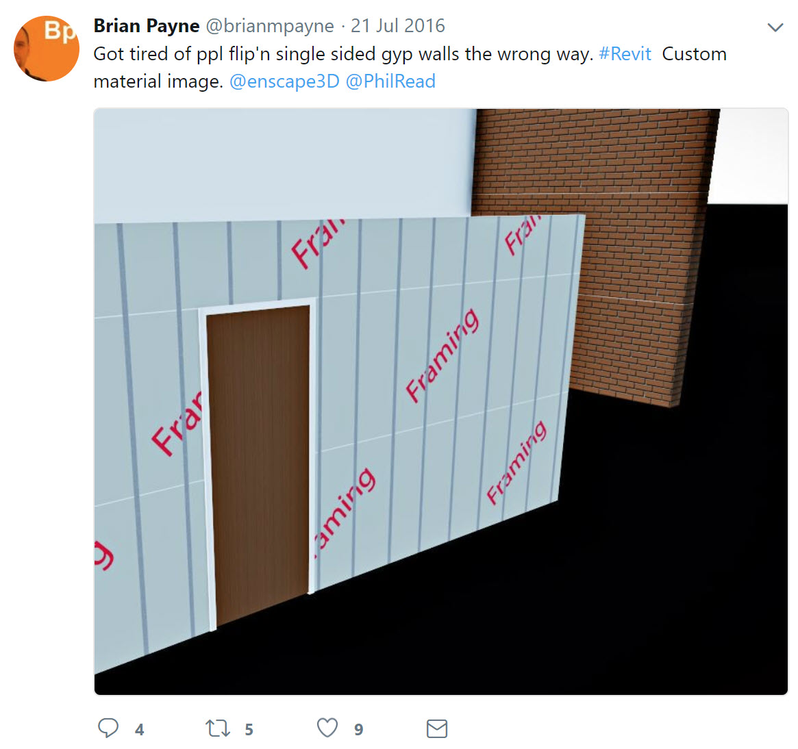
Now on to the idea I had to show the essence of studs in a Revit rendering or in Enscape. I created a special "stud layer" material which used a Cutout with two vertical lines on the left and right, and then set the image sample size to 16" square as shown in the iamge below.
Here is the image file I used. I just created this in Photoshop. You can download this image and give it a try if you want.

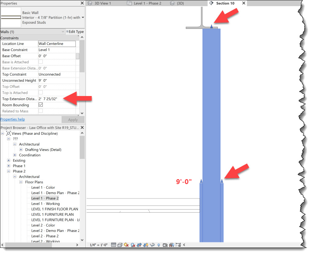
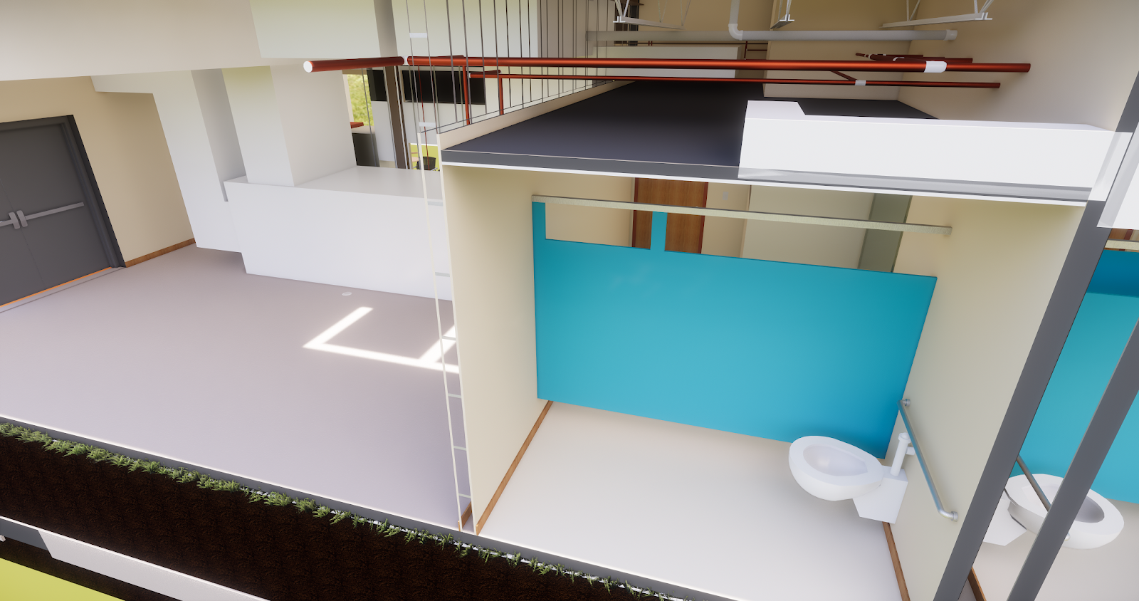
Using the two techniques just covered, I modify a wall between a toilet and mechanical room as shown in the next two images.
Notice, when the wall is selected, grips appear at the top of the Gyp Bd and the top of the stud layer. Also, compare the wall height and the Top Extension Distance parameter in properties.
When I open this model in Enscape, the material used for the Gyp Bd layer is automatically applied to the exposed stud layer (ignoring the material applied to the stud layer). So, unfortunately, I had to Paint the material on the exposed stud layer. The results are shown in the image below. Not a practical workflow.

Another interesting issue I ran into was with a furring wall. In the image below, the wall behind the AHU has a Gyp Bd layer on one side of a stud layer. The material Cutout goes all the way through the backside of the wall as seen here; notice you can see the back side of the wall cabinets in the adjacent staff break room.

However, the view from the adjacent room looks fine.

The other problem, as seen from this view above the toilet room ceiling (looking back towards the mechanical room) is that the cutout does not create sides. Thus, the studs have a front and back face, but no sides. This is the same in a Revit rendering and in Enscape - so I assume it is a Revit issue?
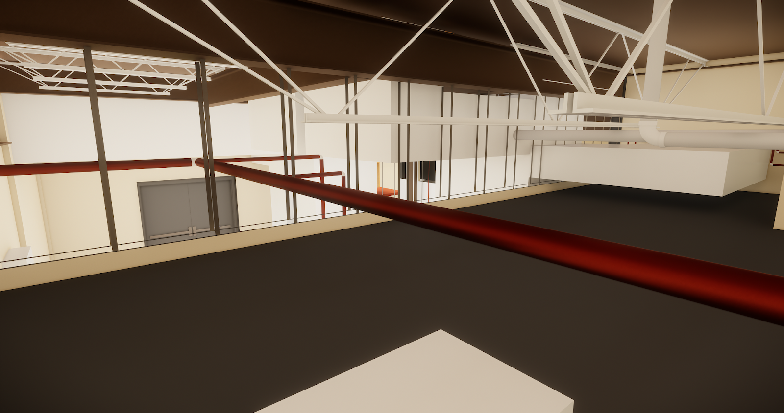
My goal is not to get studs to appear in the correct location... that is rarely ever necessary in a design model in my opinion. However, see the notion of exposed studs in a real-time Ensacpe walk-through or VR experience would be pretty cool.
Another angle...

And, a slight distraction while in Escape, just for fun...

Curious if anyone has additional thoughts on making this work in a simple way.
For BIM Chapters updates, follow @DanStine_MN on Twitter