
A new structural feature in Revit 2018.1 is the Autodesk Structural Precast Extension for Revit 2018. Available in English, French and German languages at the moment.
This feature/extension leverages Revit's Parts functionality and currently supports the design of solid walls, solid slabs and hollow core slabs (precast plank). I just said "design" but the new tool is also developed to automatically create shop drawings and export CAM files (Unitechnik and PXML) for fabrication.
Check out the detailed BIM and Beam blog post here; click here.
The extension must be download from the Autodesk App Store and then installed; after the Revit 2018.1 update I presume. The nice thing about this being an extension, I suppose, is that those not interested in this feature won't see a new tab on the ribbon that does not apply to them? However, if integrated into a future version, this could easily be a toggle in the UI section of the Options dialog.


Here is a sample image I lifted from the App Store...

Once installed, several Revit families and templates are placed in an "special" location... C:\ProgramData\Autodesk\Structural Precast for Revit 2018\Families\en. Notice, in the image below, there is also a Shared Parameters file included.

When you attempt to run the first command, you are presented with a Warning (see image below)... I am not sure it should be an alarming, and somewhat confusing, "Warning". This is basically saying some content needs to be loaded for this extension to work properly (like trying to use Revit's structural commands in one of the architectural templates, you have to use Transfer Project Standards first).

I said this warning is confusing, because I am thinking I need to go to this folder manually and load some stuff into the current model. However, when you click OK everything needed starts loading automatically with this progress bar visible (see image below). This process loads a ton of supporting families, including one called 00.rfa.

As luck would have it, the first wall I selected was not the ideal size for the preset panel sizes and accessory offsets... so I got this error; things look like the a curtain wall with rules which resulted in slivers around the edges. Fair enough, for this test I just changed the wall size and tried again with success.

Speaking of presets, here is a screenshot of the Configuration dialog... and you thought the railing dialogs were complicated!

Once I run this tool on a wall, which should be set to Structural, the individual panels are represented by Parts and visible via the view's Parts Visibility toggle. Clicking the Shop Drawing command causes Revit to create Assembly views with sheets and schedules as shown in the next two images.


In the Shop Drawing view above, each precast part has it's Center of Gravity (COG) identified. This only appears once the "shop drawing" command is run. We really need a robust COG tool in Revit. We have created some super complex truss-type elements for an industrial project in Revit and needed to export them to AutoCAD and use it's MASSPROP command to derive this information. Maybe there is a way to do thin in Robot, RISA or Dynamo (comment below!)?
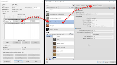
The proper material must be selected for COG to work properly... I read something about "by category" is not a good option within the wall type.
Converting a floor to precast presents this option dialog; Hollow Core Slab or Solid Slab.

Here is were I started to have some problems...
Selecting precast plank (hollow core) I got lots of errors related to the size of the selected Revit floor in the model.

So I went into the Configuration dialog and found the hollow core presets... these selections have corresponding families (hover over one to see the original path for this family on your computer).

I opened one of the profile families and found myself distracted by learning all the content is metric:) From this family, and the others preset, I learned the default thickness is 7 7/8". I did not dig too deep, but I would hope these are parametric as we use more than just 8" plank. However, changing my floor thickness to match, as a test, still did not work.
 Before finishing this post, I was not able to figure this one out... I will do another post when I do. I decided to share this information anyway, as the process highlighted more detail into how this extension works.
This feature/extension leverages Revit's Parts functionality and currently supports the design of solid walls, solid slabs and hollow core slabs (precast plank). I just said "design" but the new tool is also developed to automatically create shop drawings and export CAM files (Unitechnik and PXML) for fabrication.
Check out the detailed BIM and Beam blog post here; click here.
The extension must be download from the Autodesk App Store and then installed; after the Revit 2018.1 update I presume. The nice thing about this being an extension, I suppose, is that those not interested in this feature won't see a new tab on the ribbon that does not apply to them? However, if integrated into a future version, this could easily be a toggle in the UI section of the Options dialog.
- TIP: Save the downloaded MSI file to a shared network location so others can quickly install when needed.

Click the "shopping cart" icon (see image above) to access the App Store and the search for "precast" as shown below.

Here is what the Precast tab looks like once the extension is installed. Interesting On/Off button, were the tool tip says "Turn Structural Precast for Revit off to replenish hardware resources and improve Revit performance."

Here is a sample image I lifted from the App Store...

Once installed, several Revit families and templates are placed in an "special" location... C:\ProgramData\Autodesk\Structural Precast for Revit 2018\Families\en. Notice, in the image below, there is also a Shared Parameters file included.

When you attempt to run the first command, you are presented with a Warning (see image below)... I am not sure it should be an alarming, and somewhat confusing, "Warning". This is basically saying some content needs to be loaded for this extension to work properly (like trying to use Revit's structural commands in one of the architectural templates, you have to use Transfer Project Standards first).

I said this warning is confusing, because I am thinking I need to go to this folder manually and load some stuff into the current model. However, when you click OK everything needed starts loading automatically with this progress bar visible (see image below). This process loads a ton of supporting families, including one called 00.rfa.

As luck would have it, the first wall I selected was not the ideal size for the preset panel sizes and accessory offsets... so I got this error; things look like the a curtain wall with rules which resulted in slivers around the edges. Fair enough, for this test I just changed the wall size and tried again with success.

Speaking of presets, here is a screenshot of the Configuration dialog... and you thought the railing dialogs were complicated!

Once I run this tool on a wall, which should be set to Structural, the individual panels are represented by Parts and visible via the view's Parts Visibility toggle. Clicking the Shop Drawing command causes Revit to create Assembly views with sheets and schedules as shown in the next two images.


In the Shop Drawing view above, each precast part has it's Center of Gravity (COG) identified. This only appears once the "shop drawing" command is run. We really need a robust COG tool in Revit. We have created some super complex truss-type elements for an industrial project in Revit and needed to export them to AutoCAD and use it's MASSPROP command to derive this information. Maybe there is a way to do thin in Robot, RISA or Dynamo (comment below!)?
The proper material must be selected for COG to work properly... I read something about "by category" is not a good option within the wall type.

Converting a floor to precast presents this option dialog; Hollow Core Slab or Solid Slab.

Here is were I started to have some problems...
Selecting precast plank (hollow core) I got lots of errors related to the size of the selected Revit floor in the model.

So I went into the Configuration dialog and found the hollow core presets... these selections have corresponding families (hover over one to see the original path for this family on your computer).

I opened one of the profile families and found myself distracted by learning all the content is metric:) From this family, and the others preset, I learned the default thickness is 7 7/8". I did not dig too deep, but I would hope these are parametric as we use more than just 8" plank. However, changing my floor thickness to match, as a test, still did not work.

Enjoy!