
The use of LED strip lights, or light tape, have come a long way in recent years, and can often provide primary lighting that may need to be calculated. Today's post shows how this can be accomplished with the professional lighting add-in for Revit called ElumTools. I will show how accurate calculations can be achieved with, and without, manufacturer provided photometry.

This type of calculation has become a lot more common. However, finding an IES file for things like the LED strip tape is not always easy. Alternatively, you can build a family with a luminous material by assigning a luminance value in ElumTool's Material Mapping dialog. ElumTools will just assume a Lambertian distribution, which can be a pretty good approximation for bare LEDs without optics. When available, an IES file is obviously more accurate, if you can get one.
Using Mfr Provided Photometry
First, I will show an example when an IES file (photometry) is available.
Here is one manufacturer I found that does provide photometry for their LED strip lights: https://www.flexfireleds.com/photometric-data-ies-files/

I downloaded the 2400k UltraBright™ Architectural CRI93+ Series LED Strip Lights IES file. I created a light fixture family and attached the IES file to it.

Within ElumTools, as seen in the image below, we are able to discover the size of the fixture the test was based on; 3.28' x 3/8".
FYI: it is technically possible to make the fixture any length and then adjust the Proration Factor value to scale the light intensity accordingly, but that is more prone to error. So I just made the lighting fixture the correct size and copied it as many times as I needed.

Here are the properties, in Revit, for this family.

For my test model, I created a low recessed area to conceal the light source as shown in the following cutaway view.


Using a luminous material and specifying the lumens per foot
Now, lets look at how to calculate the same condition without the IES file. Using the same geometry as the first family, I simply paint a material onto the bottom face as shown here:
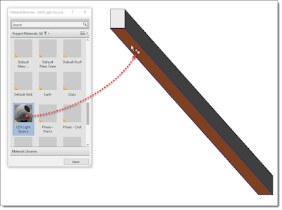
FYI: The light source is simply turned off in this family.
You typically won’t know the appropriate luminance value. But instead, you can specify the lumens per foot, which manufacturers often provide when they don’t have IES files (see this value, 329, in the third image from the top for this example). ElumTools then converts that to a luminance value.
In ElumTool's Material Mapping dialog I have the ability to specify the Lumens per foot. I must also specify the width.


The results, as seen in the two schedules below, are within 10%.

Fun stuff!
For BIM Chapters updates, follow @DanStine_MN on Twitter or connect on LinkedIn
Check out my video-based courses on ArchSmarter.
I also write blog posts for Enscape - a new paradigm in rendering, animation and VR for AEC.