

With this new workflow we can get a nearly 100% accurate representation of the existing and/or proposed surface(s) from Civil 3D. In most cases sub-regions and building pads can be added within Revit. And, because this workfow uses a link, when the surface changes the sub-regions and building pads are maintained!
Although not perfect, it is super cool and easy to use.
Read on to learn more...
A nice quote on this feature from Harlan Brumm at Autodesk:
"The new linking behavior is pretty good if you are trying just to bring in a surface and use it in Revit without grading it – you can do a lot with it, sub regions work, materials work, spot coordinates, spot slopes, hosting railings, building pads – and really the best part is that if the link updates based on changes in Civil 3D, you don’t lose all the stuff above when the link updates. Plus, the surface is 100%* correct based on the surface in civil (*there might be some tolerance with the surface depending if it is a huge site or not so exact values might be off – like .001 difference) it will support holes in the surface too (gaps made with boundary lines in Civil 3d) – stuff that is not possible with the normal topography workflow with Revit. We also simplified the coordinate workflow for the link – it either goes center to center, or with shared coordinates setup, will automatically place it correctly ,with geo location too."
Here is the workflow:
First, you must have rights to BIM 360 Docs, which is an Autodesk cloud service. Some already have this for other workflows. If you have the new Collections license model, you can get 12-months free access, called a "Preview." To learn more about the preview option, follow this link: click here.
Next, you must have a current version of Desktop Connector installed. That can below downloaded via this link: click here.
Both Revit and AutoCAD Civil 3D must be updated to 2019.1.
Now for the fun part...
In Civil 3D, select Publish Surfaces on the Output tab. I recommend you ask your Civil Engineer to do this and not do it yourself as there are many facets to a Civil 3D drawing, such as data links, xrefs and geo references - any of which could be a problem if you are just sent a DWG file. Plus, the civil engineer can re-publish the site anytime they make significant changes to the surface.

The surfaces in the file will be listed; for example, existing and proposed are often separate surfaces. They can both be selected and exported into a single surface in the cloud. TIP: This surface can be viewed in a browser via BIM 360 Docs, which is a good way to verify the correct data was exported. This is all done in the browser, which does not require any software be installed.

Now, in Revit, use the new Link Topography command on the Insert tab.

Browse to the correct Hub/Project/Folder and select the published surface...

And... here are the results! We are talking vertical retaining walls, steps and curbs all clearly coming through!

Also interesting, is the hole where the building is does not automatically get filled in with an interpolated surface (which is never accurate for and existing building). However, this means there will be no earth shown below your building in a section... but the basement will not be filled with dirt either.
Look at this surface in section... are you kidding me? This is too cool!
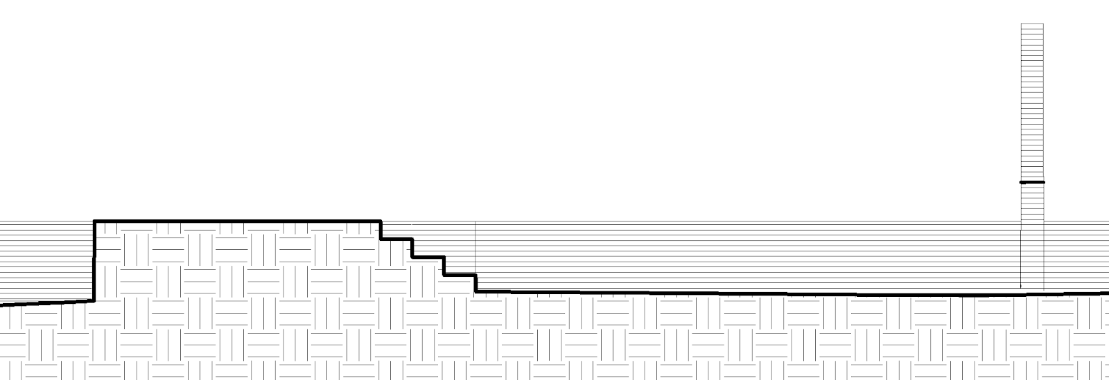
If we zoom in on the steps and loading dock area we see some anomalies. But compared to Revit's toposurface tool a vertical surface is a LOT of work, yet alone trying to create something that looks like steps!

We can see more surface definition by adjusting the "Additional Contours" Increment from 1'-0" to 0'-2" as shown here:

Here is the same view with additional contours showing. I don't think this changes the surface at all, it just adds more visual clues to define the surface.

Currently, if the surface is too complicated - like this example - it is not possible to add sub-regions or building pads. But as a V1 of a tool, this is still super cool and will help out a lot on many current projects.
I will close with a few Enscape generated images to show this element types works there. However, there is one small glitch in that material changes are not updated automatically - I that to close and re-open Enscape. And, because I cannot add sub-regions to this linked topography, as it is too complex, I can only have one material, which is set via the category in Object Styles.


Fun stuff!
For BIM Chapters updates, follow @DanStine_MN on Twitter